My Amateur
Radio SDR + QO-100 Projects
PlutoBox-3 homemade 2.4GHz TRX + 6W PA
Pluto-PA homemade 2.4GHz 30W PA
My 1. PlutoBox + 5W PA QRV via Satellite QO-100
DATV-RX MiniTiouner Pro by F6DZP
DATV with homemade PlutoBox + 60W PA
SDR-TRX + OSA103-Modul + 100W-PA + LPF
SDR-TRX RD100 + Red Pitaya + 100W-PA + LPF
Modification of my TS50S as SDR-TRX + Red Pitaya
DATV Receiver PicoTuner Pro V2

At the
beginning of 2024, my Picotuner Pro V2 was created in collaboration with Tom
ZR6TG.
Click to
see the project video

Backside of the PicoTuner Pro V2

Inside the PicoTuner. Instead of the expensive FT2232 USB modules as used in the MiniTiouner, a Raspberry Pico board is used for data transmission of the two transport streams. Later, the integrated Ethernet HAT will also be supported by the OpenTuner software from Tom ZR6TG.

PicoTuner running with OpenTuner software
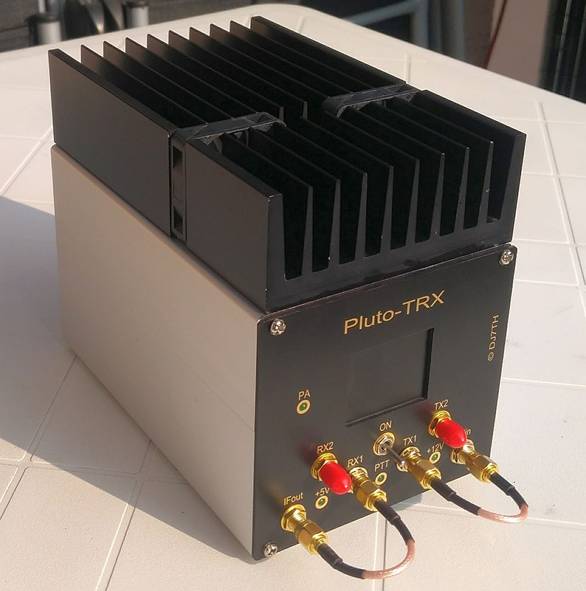
The housing with 105x95x163mm (WxHxD) consists of two stable aluminum
profile half-shells from Fischer Elektronik and is optimized for the
insertion of Eurocards with 100x160mm.
Front and back plane as well as the boards are made of high-quality epoxy
material.
The front panel labeling and all SMA sockets are gold-plated.
A sufficiently dimensioned heat sink with two temperature-controlled fans
ensures good cooling of the 20W SG Lab PA in the upper half of the housing.
The RX- and TX-boards as well as the PA are each connected via a
service-friendly manner using a pluggable 8-pin cable.
Except for the pre-assembled SAW filter and the 74HC74, only wired
components are used, which makes it possible to replicate without SMD tools.
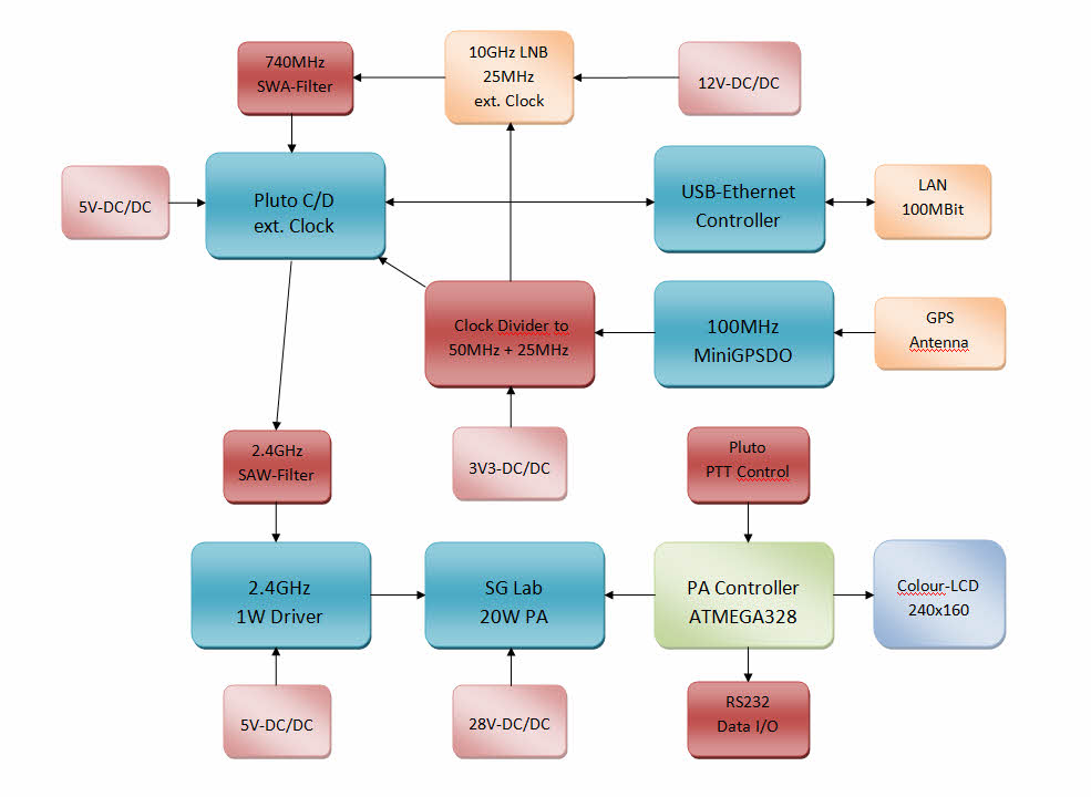
The individual components of the PlutoTRX are supplied via five
voltage-controlled DC/DC converters and make the TRX largely independent of
the voltage of the external power supply, which can be between 8V and
approx. 20V and which is an advantage for portable use. An internal 100MHz
clock generator from LeoBodnar is synchronized via an external GPS antenna
and supplies an extremely stable 50MHz clock to the Pluto via a frequency
divider, and a 25MHz clock to the external LNB via further division.
An ATMEGA328 CPU controls the most important parameters of the TRX and shows
this on a 1.8" color display. This data can also be read out via an RS232
port and, for example, transmitted to the PC via an external web server
module (optional). The setting of the TRX takes place via LAN or WLAN and via an integrated USB Ethernet
controller.The PTT signal can be taken from the backplane to control another
PA.The power supply can also be taken from there for an external device,
e.g. a DATV-RX.
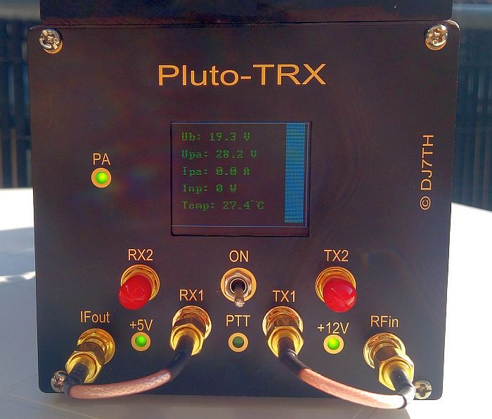
PlutoTRX front plane with gold-plated lettering
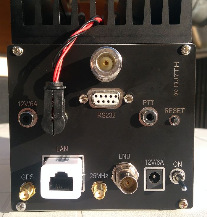
PlutoTRX backplane
RX section in lower half shell:
- Mounted ADALM-PLUTO board with 2x Rx port and 2x TX port (front plane)
- PTT logic for driver and PA control with PTT switch (front plane)
- 100MHz MiniGPSDO module from Bodnar, mounted on Pluto board
- Synchronization of Pluto via 100MHz divider and ext.50MHz clock
- 2nd divider to 25MHz + low-pass filter to synchronize the ext. LNB
- SAW filter for 2.4MHz (TX) and 740MHz (RX)
- Attenuator for TX and RX (10dB each by default)
- USB Ethernet adapter for connection to PC or LAN or WLAN
- DC/DC converter for 3.3V (CPU), 5V (Pluto), 5V (1W driver) and 12V (LNB)
- LNB connection via BNC socket with internal 12V supply + 25MHz clock
- Socket + switch for operating voltage 8..20V (max. 5A) with reverse polarity protection
- LEDs on the front panel to control 12V, 5V, 28V and PTT status
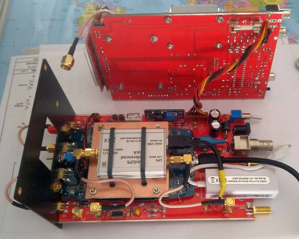
The MiniGPSDO module from Leo Bodnar Electronics is mounted on the bottom board with a 5mm gap on the Pluto board. This module generates a GPS-synchronized 100MHz clock, which is divided into 50MHz to synchronize the Pluto board and further divided into 25MHz for the LNB. Here you will also find the PPT logic, various DC/DC converters and the USB Ethernet controller. The upper board with the PA power supply is connected via an 8-pin pluggable cable.
TX section in upper half shell:
- 20W 2.4GHZ PA module from SG-Lab enhanced with SWR + RF output +
temperature sensor
- 1W 2.4GHz driver module with 40dB gain
- 28V DC/DC converter for PA with 12V fan
- Digital monitoring of the 20W PA and PA shutdown via 28V relay
- Additional PA protection by 33V ZORP diode + 10A line fuse
- Heat sink 40x100x150mm with two integrated 12V fans
- Control of the external 12V fan on the massive heatsink
- 12V socket + PTT socket (backplane) for ext. Devices
- Operational data output on RS232 port (backplane)
- Display via 1.8" LCD color display and monitoring of:
- Operating voltage (8…20V)
- PA voltage (28V)
- PA current (0-2A)
- PA DC input (0-60W)
- PA temperature in °C
- PA RF output (vertical green bar)
- PA-SWR (vertical red bar)
- Error messages and alarm output via mini loudspeaker
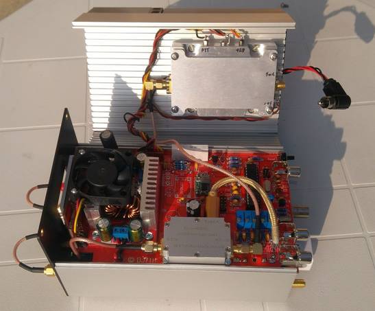
TX board with 28V DC/DC converter, 28V relay, attached 1.8" color display + fan,
ATMEGA328 CPU and 1W 2.4GHz driver module.
The 20W-PA sis mounted in the upper half-shell.
Downloads: Pluto-Board, PA-Board
Firmware and application software:
The original firmware of the Adalm Pluto will be exchanged with the DATV
enhanced firmware 0303 from Evariste F5OEO and an additionally
Patch by
Christian F5UII to enable the PTT function with the C/D version of the
Pluto.
I wrote the firmware for the ATMEGA328 CPU with the ARV-BASCOM compiler.
Alternatively, you could also use a development environment for the Arduino,
since it uses the same CPU.
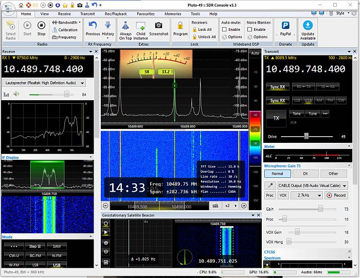
The current version of the SDR Console program from Simon G4ELI has proven its worth as user software - not only for transponder operation - also with SSB and digital operating modes.
PlutoBox-3 homemade
2.4GHz TRX + 6W PA

At the end of May 2022 I put my PlutoBox Version 3 into operation. The complete 2.4GHZ TRX is housed in a stable aluminum profile housing from Fischer Elektronik Germany, consisting of two half-shells with the dimensions 105x160x64mm. Several internal DC/DC converters generate 5V for the Pluto, 3.3V for the OCXO and 12V for the LNB. Thus, a stable operation of the TRX with an external power supply of approx. 8V to approx. 16V is possible.
In addition to the Pluto Rev. C/D, the PTT electronics are on a 100x160mm double-sided printed circuit board, as well as an homemade 100MHz VOCXO, that can be calibrated on the front panel, consisting of an 100MHz VCXO + CPU controlled heater in a small box. Further a 100MHz frequency divider, an ATTINY CPU for controlling the heating of the VOCXO and an USB Ethernet adapter. As an alternative to the 100MHz OCXO, you can switch on the backplane to an internal 100MHz signal generator from Bodnar which supplies an extremely precise 100MHz clock, with GPS synchronization by an external GPS antenne.
The 100MHz clock is divided to 50MHz and fed to the Plutos external clock input, further divided to 25MHz in order to make it available as a clock signal at an SMA socket on the backplane to a correspondingly modified LNB and switchabel to the LNB plug too.
The LNB RX signal (BNC-Connector) is fed to a 740MHz SAW filter + 10dB attenuator, via the front panel connector IFout and an SMA cable to Plutos RX1 Input. This achieves good suppression of interference signals outside the RX range and higher sensitivity of the RX. Plutos RX2 and TX2 connectors are also fed to the front pannel, but not yet supported by software.
The Plutos TX1 output signal goes via an SMA cable to the input-port RFin of the 2.4GHZ SAW filter and to the built-in 6W PA module from AMSAT-DL, mounted on an aluminum board for better cooling (see below).
Downloads: PlutoBox Schematics PlutoBox-3 Beschreibung in deutsch

Backplane
The TX antenna cable can
be connected to the SMA socket RFout on
the backplane.
There are also sockets for the external power pack
(8..16V) with power switch, a GPS antenna connection,
a PTT port
and 8..16V output for an external PA, but limited to max. 6A.
The Pluto is controlled via the built-in
USB Ethernet adapter, which enables it to be integrated into a LAN
environment using a LAN cable of any length or directly connected to a PC or
Notebook. I use F5OEOs Pluto Firmware 0303 and IS0GBR patch 2.1 for DATV and
the well-known Windows program SDRConsole 3.2 by Simon Brown as operating
software for SSB and digital modes (Narrow Band). With my 1m dish
(see below) I can generate a signal on the QO-100 that is about 5-6dB weaker
than the lower beacon.

Adalm Pluto Version C/D mounted on my Controller-Board

6W AMSAT-DL PA + Bodnar 100MHz GPSDO mounted on an Aluminium-Board

Testing the 6W PlutoBox TRX + GPSDO via QO-100
Pluto-PA
homemade 2.4GHz 30W PA
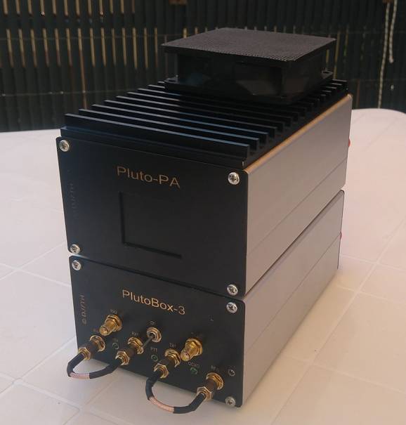
Front View 2.4GHz TRX PlutoBox-3 + 30W Pluto-PA
Parallel to my PlutoBox-3, which was put into operation at the end of May 2022, I had completed the current version of my 30W Pluto-PA. The complete PA is housed in the same aluminum profile housing as the PlutoBox-3 with the dimensions 105x160x64mm, consisting of two half shells with a front and a back plane. Several internal DC/DC converters generate 28V for the PA module, 3.3V for the ATMEGA CPU and the display, and if required 5V for an optional 1W driver module.
The PA can be
operated with an external power supply of approx. 8V to approx. 16V and is
normally taken from the PlutoBox-3 using a cable bridge (see photo). The
controller electronics with an ATMEGA328 CPU, as well as the 28V DC/DC
converter with fan cooling and an optional 1W driver module are located on a
100x160mm double-sided controller board. The color graphics display with
128x160 pixels is designed as a plug-in module and is located directly
behind a front panel cut-out.
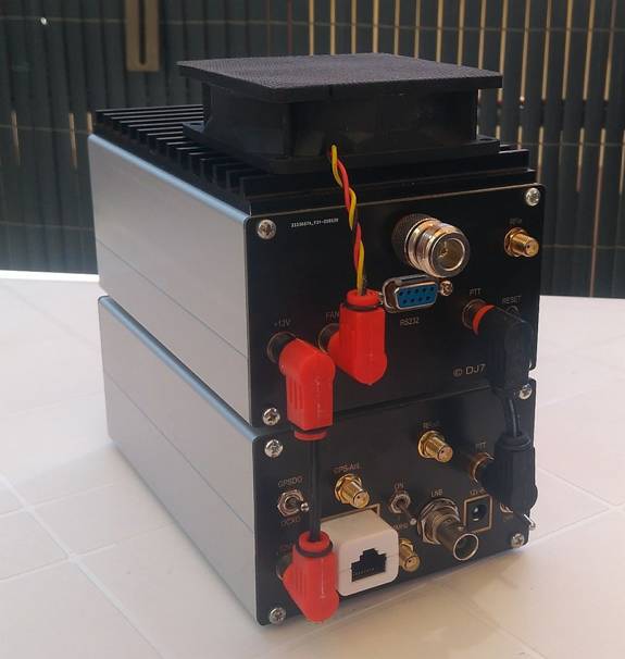
Backplane
The connection sockets for +12V, PTT, external fan, RF input, RF output as well as an RS232 port for optional data transmission and the reset button are located on the backplane.
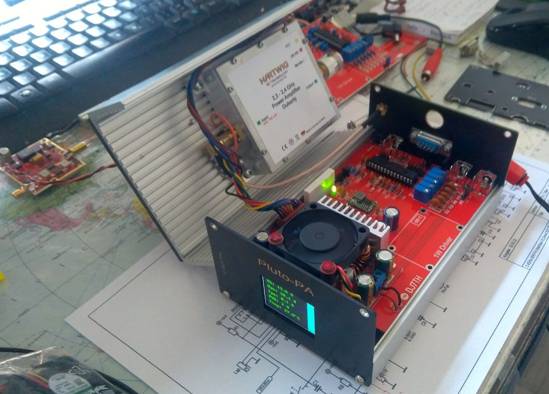
Inside the 30W Pluto-PA
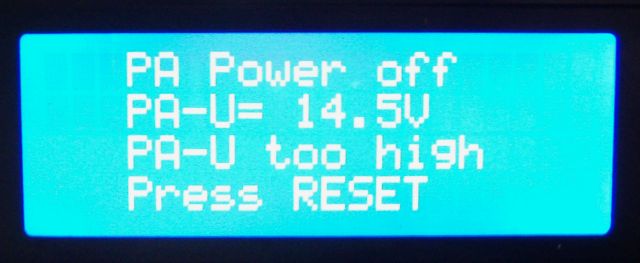
The 30W PA-Module made by Rüdiger Hartwig is screwed to the upper half of the housing. A heat sink with a temperature-controlled fan ensures sufficient cooling during continuous operation. The PA temperature is monitored by the CPU and the fan is controlled via a temperature sensor mounted under the PA-Module. If the temperature is too high, the 28V are switched off immediately and an error message appears on the display. The switch-off also occurs in the event of over- or undervoltage of the 12V and if the PA current or SWR is too high.
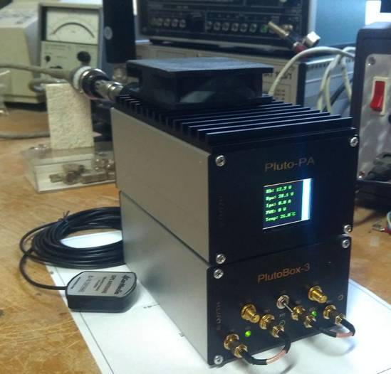
Pluto-PA Test
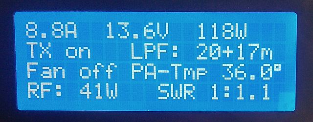
The following calibratable values are shown on the color graphic display:
- Power supply voltage (Ub as xx.x V)
- Voltage of the DC/DC converter (Upa as xx.x V)
- Current consumption of the PA (Ipa as xx.x A)
- PA input power (Pin as xxx W)
- PA temperature as xx.x °C
- Two vertical bars show output power and SWR
As an option, all
measured values can be transmitted via the RS232 port directly
or via
WiFi to a connected PC or Notebook.
Downloads: Pluto-PA Schematics
Pluto-PA
Beschreibung in deutsch
DATV with homemade PlutoBox +
60W PA

Inside my modified 60W Radiocomp-PA and my homemade power supply.
The PA has two identical 30W push-pull output stages + drivers. Originally the Radiocomp-PA had run as a UMTS mobile station on approx. 2.6 GHz. The complete RX-module and the power supply were removed and replaced by two 12/28V step-up controllers and a 230V/12V switching power supply.

My Radiocomp PA completely assembled, connected to my PlutoBox and tested
step by step.
DATV-Receiver MiniTiouner Pro by F6DZP

The MiniTiouner Pro developed by Jean-Pierre F6DZP served as a template of my schematic.
More information from F6DZP can be found here:
http://www.vivadatv.org/viewtopic.php?f=83&t=442

The LEDs on the front panel are used to control various voltages and signals.
The LNB voltages of the two inputs can be switched manually between 12V-0V-18V.

DATV-RX board in top view. I consistently used only wired components and a few inexpensive modules from Far East. The SERIT NIM tuner has two inputs. F6DZP MiniTiouner software should later support both inputs and enable the reception of two transmitters at the same time. The board can be supplied by external 8...20V and/or by USB-Ports with +5V, selected by some jumpers.

Version 2 with a new front- and backpanel

Version 2 with a modified power supply.

Version 3 with a modified front- and backpanel

F6DZP MiniTiouner Pro software in action
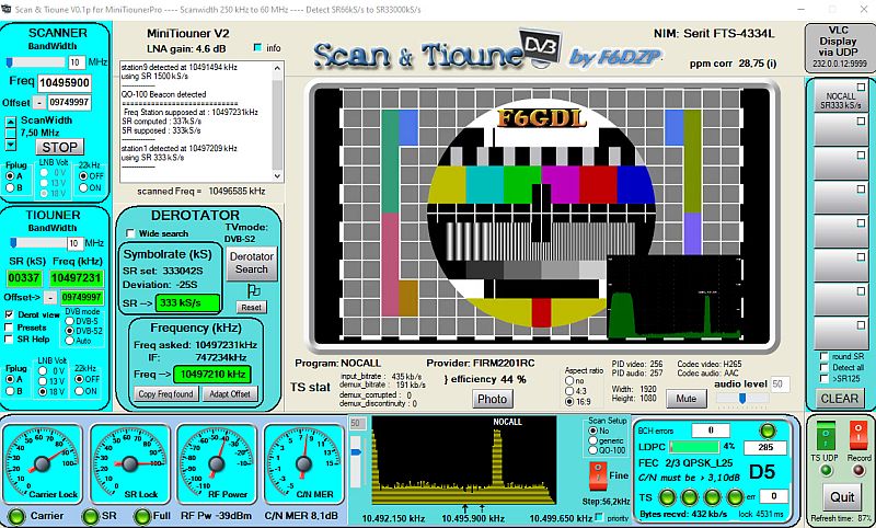
F6DZP Scan & Tioune software in action
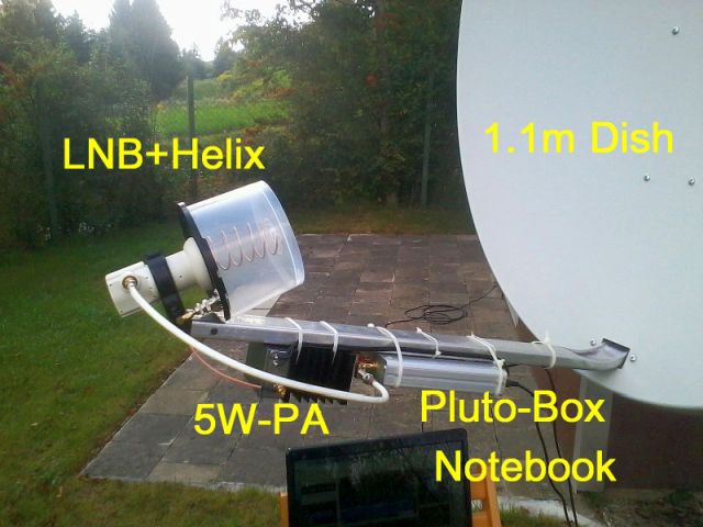
My 1. PlutoSDR + 5W-PA + 1.1m offset dish
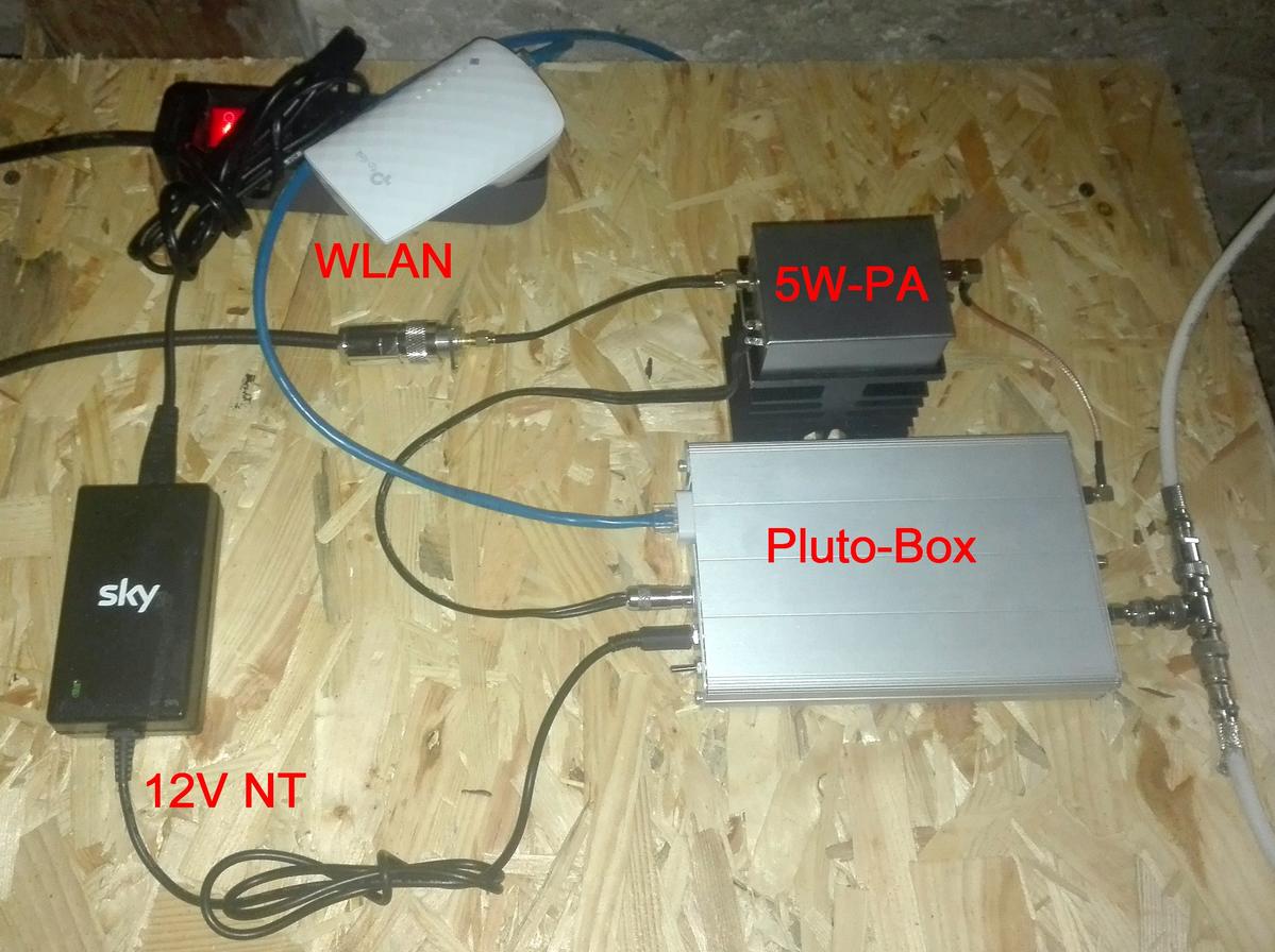
Testing my QO-100 station at my portable location in Lahr JN38WI.
The complete station is running with 12V. As software I'm using SDR Console V 3.xx.xx.
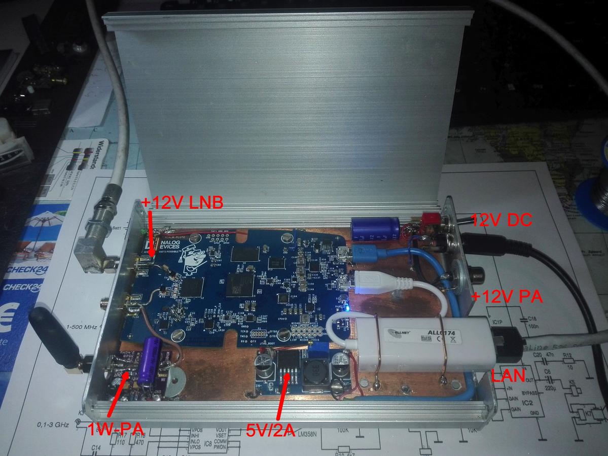
My Plut-Box running with about 1W output and connected to 12V DC and WLAN.
The 1W PA with >30dB gain is an idea of DB4UM. For better stability I changed
the original 40 MHz TCXO against a type with 0.5ppm. Here the diagram of my box.

Find more informationen about Adalm Pluto Board here:
https://www.mouser.co.uk/new/Analog-Devices/adi-adalm-pluto/
and here about Software SDR Console:
https://www.sdr-radio.com/Radios/Pluto
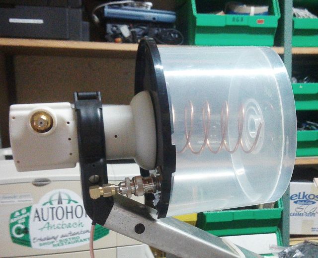
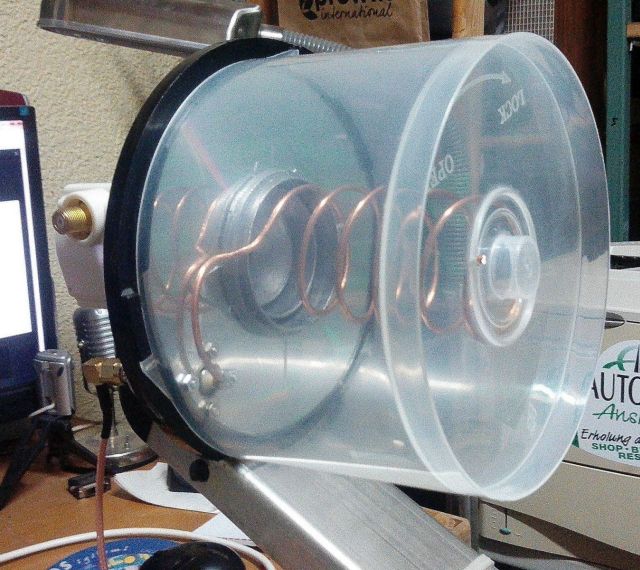
My 13cm home made helix antenna with 5 turns in a CD-Box with a CD as
reflector.
The box is mounted and fixed on a modified LNB GM 201S+
Here a link to the helix calculation tool:
https://www.changpuak.ch/electronics/calc_12a.php

My 2.4GHz home made helix antenna with 4.5 turns in a CD-Box with a cutout
epoxy board as reflector. The box is mounted and fixed on a modified LNB
Golden Media 201. The antenna is calibrated and the SWR is measured with
help of my RF VNA
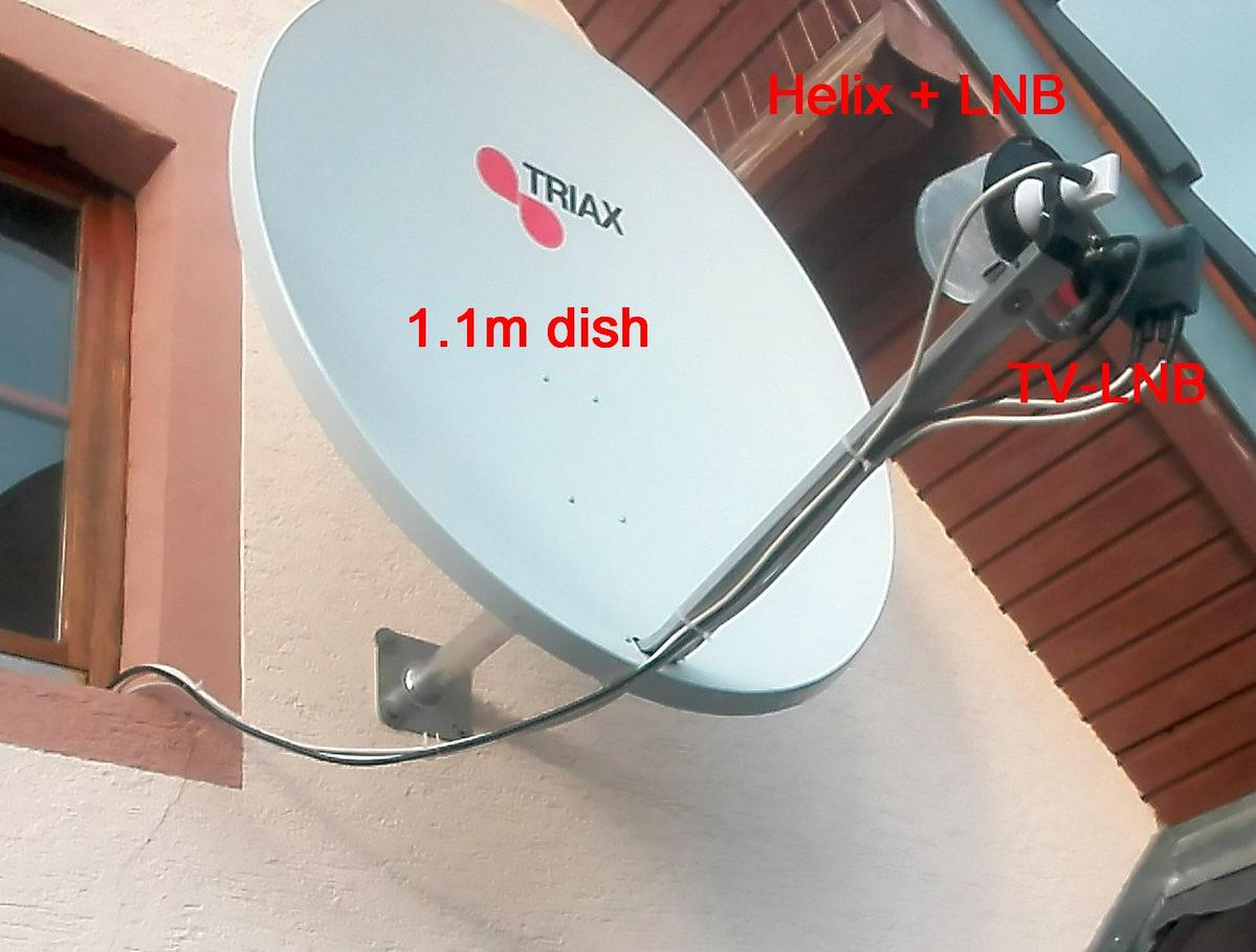
The 1.1m offset tv dish outside my home. The TV signals are also much better now,
hi.
My first complete QO-100 Station inside my home, connected to my network
via WLAN
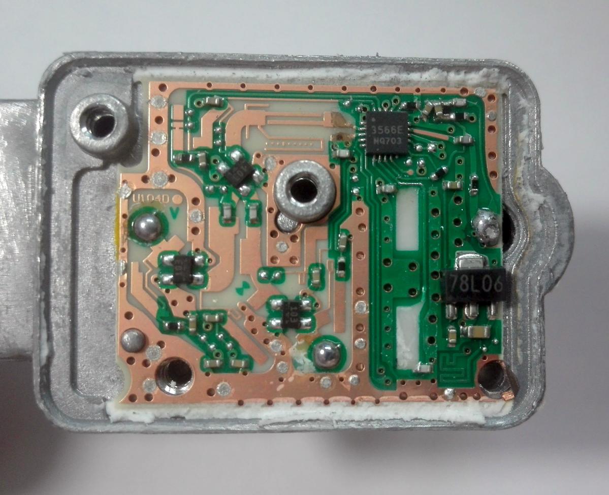
Inside LNB Golden Media 201S+ with removed 25 MHz quartz
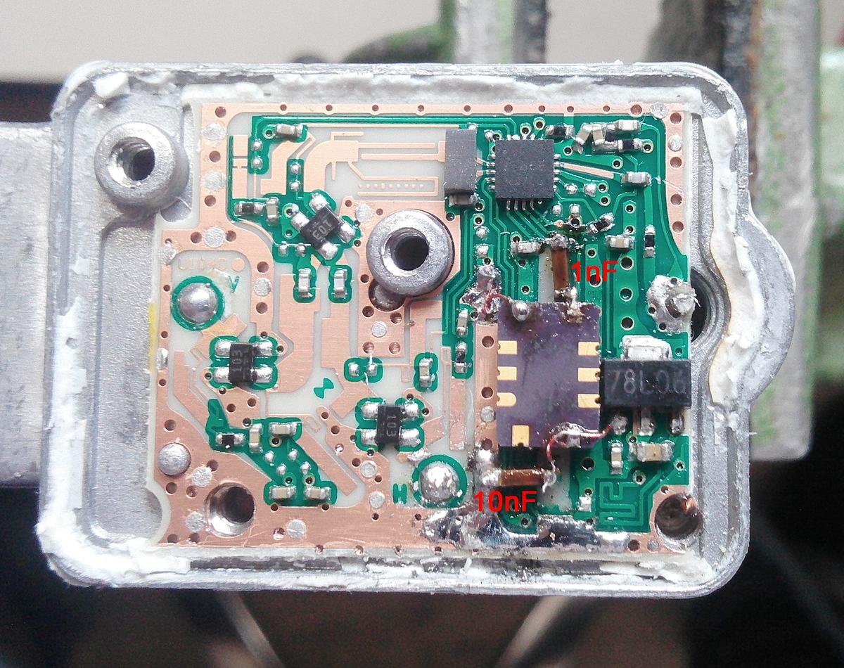
Inside LNB Golden Media 201S+ with 25 MHz TCXO D75F-025.0M
(Conner-Winfield).
The TCXO is connected to +6V. The datasheet says that
it's allowed and it works fine.
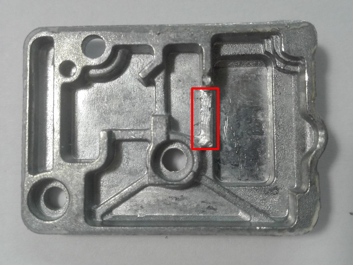
Cover of LNB Golden Media 201S+ with a cutout for the
TCXO
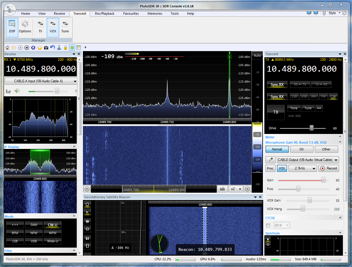
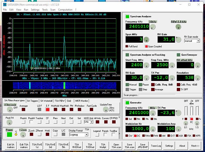
SDR Console is synchronized with the upper Beacon of QO-100 on
10489.800MHz.
This check is running in mode CW-U. The drift of the
Pluto-RX + LNB is only -166Hz
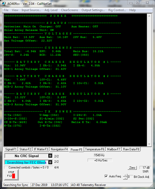
The program AO40Rcv shows
the signals from this Beacon as text pages..
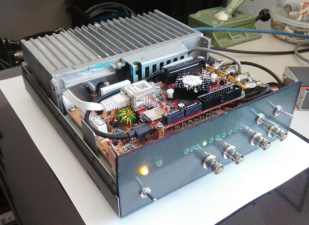
SDR-TRX
+ OSA103-Modul + 100W-PA + LPF
Parallel to the development of a complete KW transceiver with integrated low-pass filter and a 100W-PA based on the Red Pitaya module STEMlab 125-14, I started in May 2018 with the adaptation of my interface board to the OSA103 module of a Russian manufacturer. In contrast to the Red Pitaya module this module runs with the HDSDR software 2.70 and alternatively with the Zeus radio software 2.9.3. The OSA103 module has only one input and one output, but it can be used in the range of 150MHz, which I still have to test.
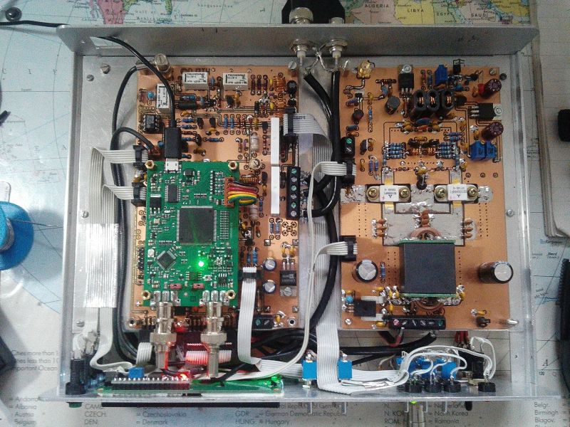
on the left the OSA103 interface and on the right the 100W-PA. Both have the size 100x160mm
This SDR-TRX is also designed for 12V operation and is therefore well suited as a compact portable station thanks to its low weight. To control the OSA103 module it has to be connected via USB cable to an external PC or notebook, on which the SDR software is running. The Mike is connected directly to the TRX. Like the Red Pitaya interface, there's a broadband amplifier to increase the RX sensitivity.
Antenna switching for antenna 1 or 2 as well as switching the 20dB attenuator are done manually on the front panel. The input and output of the OSA103 can be accessed via switch on two BNC sockets on the front panel and it can be used as network analyzers, oscilloscopes, etc.
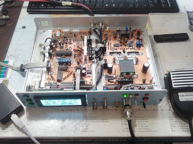
The LCD display has 4 lines with 20 characters each. With keys up-down-ok you can select various displays and monitoring functions of the PA. The wiring consists largely of flat cable connections, in addition, only wired components were used, which facilitates the replica significantly. The 100W PA and the low-pass filter are the same as I'm using it in my Red Pitaya SDR TRX. In the PA output stage the proven 12V transistors RD100HHF1 (Mitsubishi) were used. The front panel and the case will be slightly redesigned.
Picture of the structure and programming of the ATMEGA328 CPU
.Details of the (preliminary) circuit can be found here (pdf-files):
OSA103-Interface-Board
100W-PA
Low Pass Filter
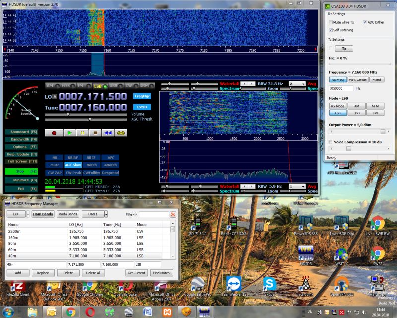
RX testing with HDSDR
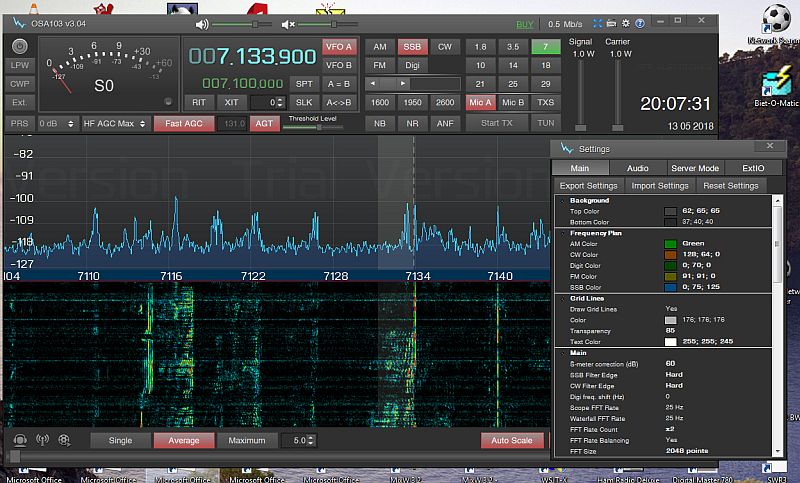
RX testing with ZEUS on 40m
SDR-TRX
RD100 + Red Pitaya + 100W-PA + LPF
After the sucessful modification of my old TRS50S TRX into a
SDR-TRX with the
Red Pitaya module
STEMlab 125-14, I decided in 2017 to develop
my SDR TRX RP100 with integrated low-pass filter and a compact
100W PA with preamplifier and driver.
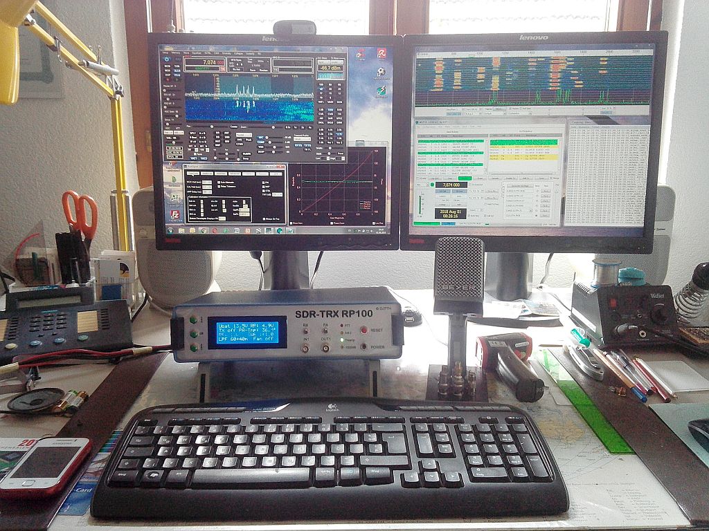
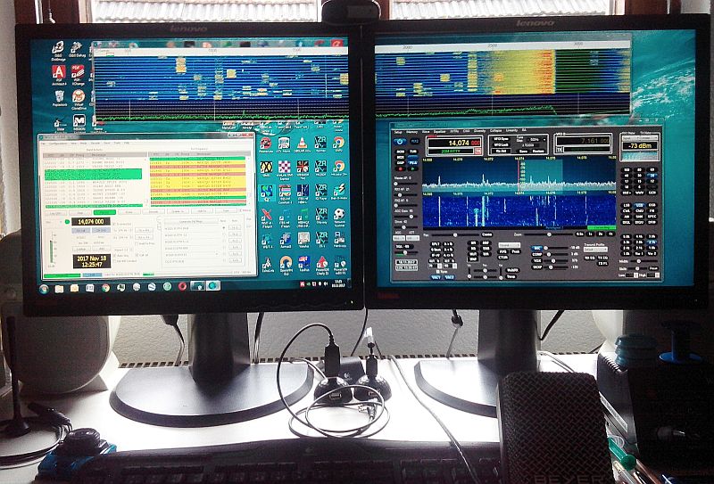
My SDR-TRX running in FT-8 mode and PowerSDR (HPSDR)
The SDR-TRX is designed for 12V operation and is therefore also
well suited as a compact portable station thanks to the low
weight of the aluminum housing. The TRX functions are controlled
by
Pavel Demin's Red Pitaya software in conjunction with the
openHPSDR software, which runs in various versions on a PC,
notebook, tablet or smartphone. For the local connection, I use
the existing Ethernet network and my wireless router. I can also
remotely control the TRX. In portable mode, the connection is
made via a directly connected 12V WLAN router and my notebook or
my tablet. Depending on the size and processor performance, a
smartphone is also suitable as an operating device, whereby I
recommend the use of a headset.
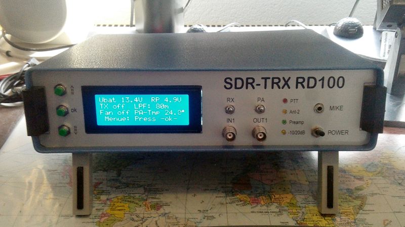
The picture shows my RD100 prototype TRX in test mode. The 4x20 LED front panel display is showing the operating states of the PA, which are detected and controlled by an Atmega328 CPU on the interface board. The BNC sockets on the front panel can be connected to IN1 and OUT1 of the Red Pitaya and can also be used for other purposes such as Vector network analyzer etc. On the back panel are two SDR software switchable antenna ports, an Ethernet port and a 12V connector.
The circuit diagrams of the Interface-Board, the Lowpassfilter and the 100W-PA can be downloaded as pdf file. The installation of all components in a slightly larger housing with redesigned front panel is in work. The prototype boards were all made by hand and would later be commercially produced after successful test operations. To facilitate the replication, only common and wired components were used.
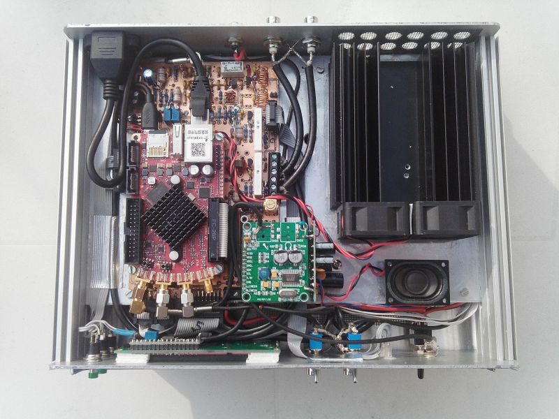
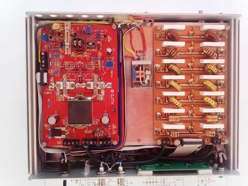
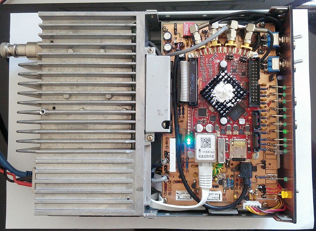
On the left side the interface board with
the Red Pitaya board and the Codec board attached,on the right
the air cooled heatsink of the 100W PA and a small
audio-amplifier + loudspeaker . The service-friendly wiring is
carried out with pluggable flat cables or terminals and SMA
connectors. The board is attached on the aluminum chassis by 4
screws.
On the bottom side are mounted the 100w PA, the low-pass filter
and the wiring with a 12V PA relay. The low-pass
filter is controlled by the decoded signals of the Red Pitaya.
The 12V power supply via a 25-pin connector on the back
panel also allows a controlled external 12V supply of other
devices (antenna tuner, etc.) by appropriate wiring.
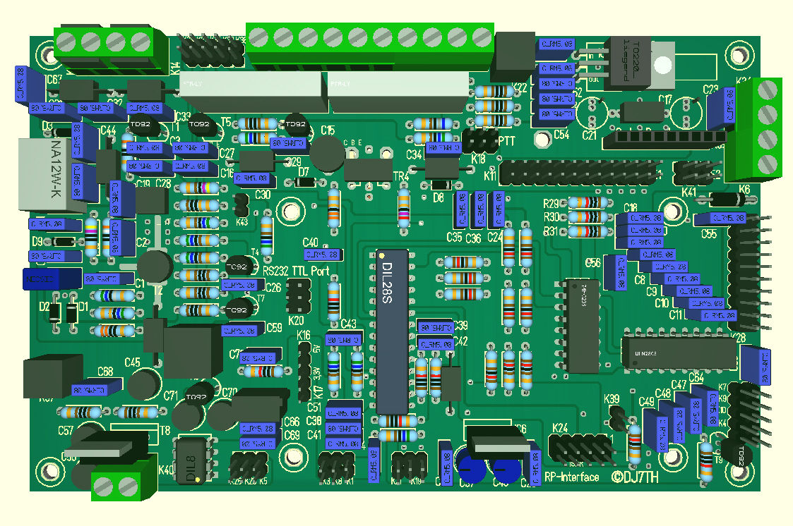
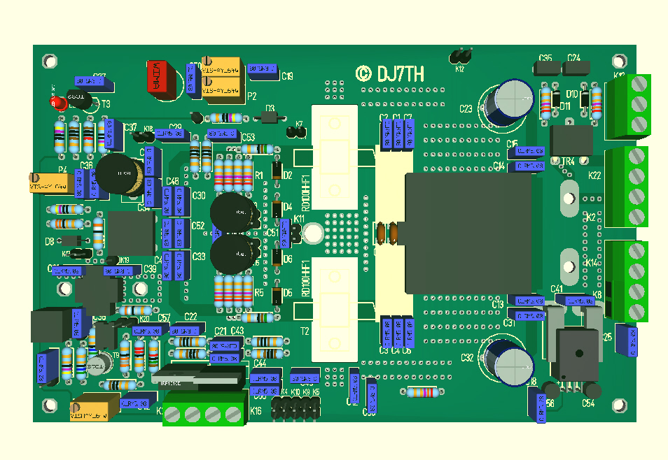
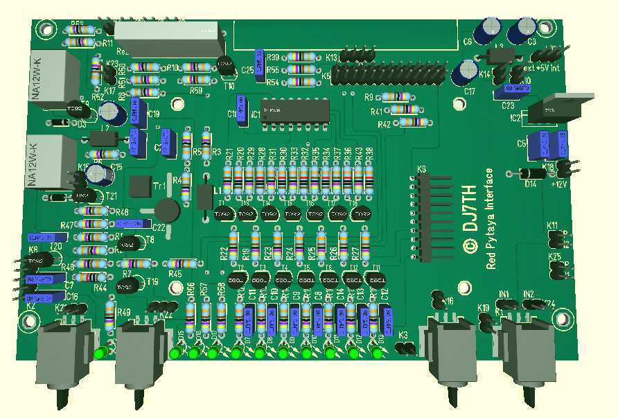
3D view of the
interface-board with ATMEGA328P
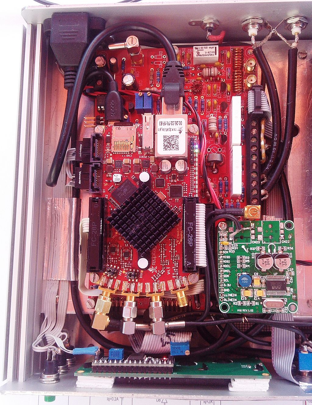
Interface-Board mounted and wired with an optional Codec-Board
The signal connection of the interface board to the other boards
and to the LCD display is made by plug-in flat cable, which
significantly reduces the wiring work and sources of error (I
hope :-). In the middle I placed the Atmega328A-CPU which I
programmed with the help of
BASCOM.
The CPU monitors the operating states of the PA, supplies the
values to the 4x20-line LCD display as well as to an RS232
interface, controls the 12V PA relay and the PA board. The Red
Pitaya module is mounted on 4 standoffs and connected to the
interface board via flat cable, also the Codec board in the
upper right corner nearby to the 5V power supply. As can be seen
in the diagram, are on the board a software switchable Rx preamp
with a low-pass filter and a two-stage attenuator, the complete
TRX
switching with SWR metering and an antenna switch relay. The
low-pass filter control signals of the Red Pitaya are decoded by
2 ICs and control the low-pass filter via a 10-pin connector.
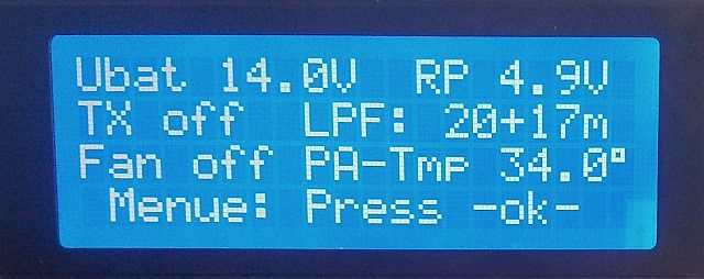
Rx-Mode Tx-Mode
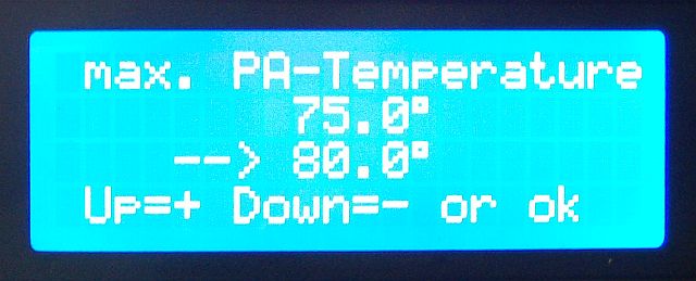
The LCD display with 4x20 characters shows: PA current, PA voltage (12V), RP (5V), Tx on/off, PA temperature, PA output power, SWR on the antenna connector, PTT on/off, the selected low-pass filter. In addition, limit values for PA current, PA temperature, PA 12V and SWR are monitored and, if exceeded, the PA is switched off and, as a precaution, disconnected from the 12V line via the relay until the Atmega CPU is restarted via reset or off-on switch. The limit values can be queried at any time via the menu with the three left keys, changed in specified ranges and saved again in the EEPROM of the Atmega CPU. Via an optional RS232 port on the interface board, you can externally display and evaluate the operating values.
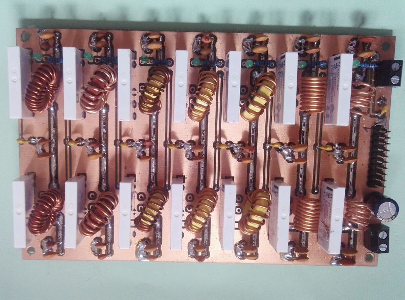
Prototype-Board of the Lowpass-Filter 160m - 6m
 3D-view of the 100W-PA with 2x RD100HHF1

Testing my 100W PA-Board
The 100W PA has been designed with 3 stages to boost the 10mW from the Red
Pitaya to 100W Rf output. To monitor and display the power consumption,
an IC type ACS756 (bottom right) is switched to the PA power supply and
connected to the interface board along with other signals such as +12V and
PA temperature. This allows to measure lossless currents up to 50A. Various
jumpers are used for individual shutdown and adjustment of the bias currents
of the PA and driver transistor. In the event of overloading or exceeding
limit values, the interface board switches off the PA and the 12V supply of
the PA.
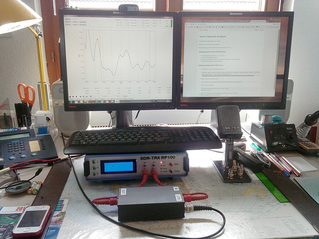
With my additional external VNA adapter and the
VNA-Software from Pavel Demin I measure the SWR of my Windom antenna.
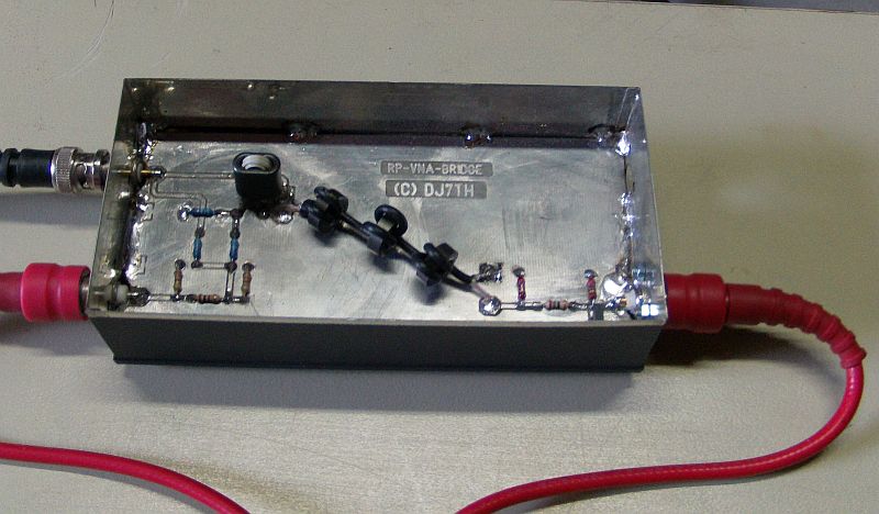
Inside view of my VNA-Adapter. Here the
circuit diagram as pdf file.
Modification of my TS50S as SDR-TRX + Red Pitaya
My disused KENWOOD TS50S RF-TRX was modified to a Red Pitaya SDR-TRX, after the removal of the partly broken RF and digital boards, using Pavel Demin's Red Pitaya firmware which is adapted to the openHPSDR software. I placed the Red Pitaya module with spacers on my interface board and connected it by a flat cable. Two flat cables on the bottom side connect the interface to the PA unit with low pass filter unit and the power supply of the TS50S.
The original front panel of the TS50S has been replaced with a simple one of epoxy material. The 4 BNC sockets can I switch to the inputs and outputs of the Red Pitaya module. The LED row indicates various operating states and the software selected low pass filter. The LAN socket sits on the back wall. There are also the original antenna and 12V connectors.
FT8 mode running on 20m
My interface board has the size of 100x160 mm and 2 layers. As can be seen on the circuit diagram (pdf-file) the control signals of the Red Pitaya are connected to socket E1 and generate the signals for the on/off control of the preamp, PTT and the low-pass filter relays of the TS50S, decoded by an IC type 74HC238. A 5V low noise switching regulator supplies the board and the Red Pitaya via a USB cable.
A software controlled RX preamp increases the low RX sensitivity
of the Red Pitaya input. The two RX inputs of the Red Pitaya are
switchable to the BNC connectors, so I can use the Red Pitaya
for other purposes, such as a vector network analyzer. There is
also a switchable RX attenuator, as well as an optional antenna
relay for switching between two antennas, both can be controlled
via SDR software.